
Shopping Cart
There are no more items in your cart
- News
- 0 likes
- 72 views
- 0 comments
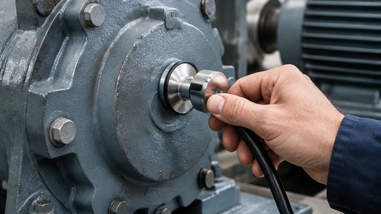
In industrial manufacturing, rotating machinery serves as the heart of day-to-day operations. Whether driving high-pressure slurry pumps, continuous heavy conveyors, chemical process compressors, or heavy-duty induction motors, bearings carry the primary mechanical load and govern rotational stability. Under ideal conditions, these precision components operate smoothly, quietly, and with minimal kinetic disturbance. However, operational wear, dynamic loads, and subtle installation discrepancies inevitably generate oscillations known across maintenance departments as bearing vibration.
Vibration is essentially mechanical energy attempting to dissipate through machine housings, structural foundations, and surrounding structural steel. Rather than viewing periodic motion as an isolated annoyance, experienced reliability engineers recognize bearing vibration as an early warning system. Long before a bearing seizes, suffers catastrophic cage collapse, or generates noticeable heat, the physical impacts between rolling elements and raceways produce distinctive vibration spectra.
Ignoring these kinetic signatures almost always leads to secondary collateral damage. What begins as a minor localized defect quickly accelerates through accelerated fatigue, damaging costly motor shafts, degrading gear teeth mesh, ruining mechanical seals, and leading to catastrophic unscheduled plant outages. Systematically understanding what causes bearing vibration empowers maintenance teams to shift from stressful reactive fire-fighting to proactive, predictive machinery management.
Our Products: Ball Bearings
The Physics of Bearing Vibration: How Oscillations Develop
To effectively diagnose abnormal motion, technicians must comprehend how bearing vibration initiates inside rolling contact zones. In a perfectly aligned and balanced rotating system, the rolling elements transition through the primary load zone supported by a microscopic elastohydrodynamic fluid film. This thin layer of oil or grease prevents direct asperity contact between the polished steel components.
When mechanical defects emerge, this continuous hydrodynamic support breaks down. If a rolling element passes over an imperfection such as a tiny fatigue crater, a deep scratch, or an indentation caused by particle contamination, it experiences an abrupt impact force. This impact transmits an impulse through the bearing rings and into the bearing pedestal. Because the machine operates at a steady rotational speed, these physical impacts repeat with mathematical periodicity, creating cyclical frequency spikes.
In the earliest stages of mechanical degradation, the localized energy released by these micro-impacts generates very low-amplitude, ultra-high-frequency stress waves. These stress waves propagate through the structure and can initially only be captured using specialized high-frequency demodulation and acceleration peak techniques. Over time, as repetitive stresses expand micro-cracks into noticeable surface flaking, the kinetic energy intensifies and migrates into conventional vibration velocity frequencies that plant technicians can easily measure with standard vibration meters.
Major Root Causes of Bearing Vibration
While mechanical vibration is the symptom observed on a data collector, the underlying root cause can stem from internal bearing wear, inadequate lubrication, improper installation practices, or dynamic forces originating outside the bearing itself.
| Root Cause Category | Primary Mechanical Trigger | Direct Vibration Signature and Machine Behavior |
|---|---|---|
| Internal Component Wear | Raceway fatigue flaking, roller spalling, or cage breakage | High non-synchronous bearing defect frequencies with sidebands |
| Dynamic Unbalance | Dirt accumulation, missing rotor weights, or bent shafts | Strong synchronous vibration running precisely at 1X operating shaft speed |
| Mechanical Misalignment | Angular offset, parallel offset, or thermal shaft growth | Strong 1X and 2X rotational peaks with elevated axial vibration |
| Mechanical Looseness | Loose mounting bolts, worn housing fits, or excessive internal clearance | Multiple harmonics running at 2X, 3X, 4X up to 10X running speed |
| Lubrication Breakdown | Dry running, severe grease shearing, or fluid contamination | Elevated high-frequency noise floor and erratic acceleration spikes |
1. Internal Bearing Defects and Subsurface Fatigue
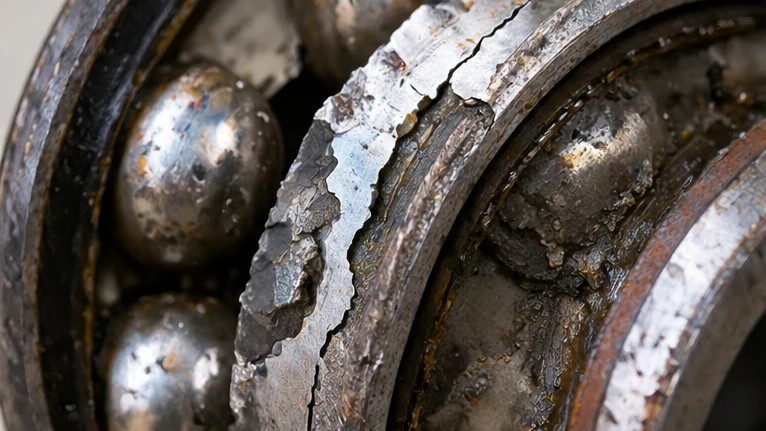
Internal degradation occurs when dynamic stress cycles exceed the fatigue limit of the bearing steel. The repeated transition of balls or rollers through the load zone induces alternating shear stresses just beneath the metal surface. Eventually, micro-cracks propagate toward the surface, causing microscopic pieces of metal to break away in a phenomenon known as flaking or spalling.
Every time a ball rolls over an outer raceway crater, an inner ring spall, or a damaged roller surface, it creates a distinct cyclical shock wave. As damage expands, the cage supporting the rolling elements begins to twist and rattle, ultimately cracking and producing intense, chaotic non-synchronous vibration patterns that signal imminent structural failure.
2. Rotor Unbalance and Residual Eccentricity
Rotor unbalance is among the most frequent external forces driving elevated bearing vibration. In electric motors, industrial blowers, and pumps, the center of mass must align precisely with the geometric axis of rotation. When dirt deposits accumulate unevenly on fan impellers, balance counterweights fall off, or pump impellers suffer cavitation erosion, the geometric and mass centerlines separate.
This eccentricity generates a powerful centrifugal force that increases exponentially with machine operating speed. The bearing is forced to restrain this whirling centrifugal force on every rotation. As a result, the vibration meter registers an intense, dominant vibration spike running at exactly the primary shaft rotational frequency, commonly referred to in predictive maintenance as the 1X running speed frequency.
Our Products: Deep Groove Ball Bearings
3. Machine Misalignment and Coupled Angular Offset
Coupling misalignment occurs when the driven shaft and the driving motor shaft do not share a common rotational centerline. Misalignment appears in two primary configurations: parallel offset, where the shafts run parallel but on different planes, and angular misalignment, where the shafts meet at an intersecting angle. In field environments, machines often exhibit a complex combination of both.
When shafts are misaligned, the flexible coupling attempts to absorb the angular deviation by flexing on every half-rotation. This cyclic binding imposes severe static and dynamic bending moments directly onto the machine bearings. Bearings subjected to severe misalignment typically exhibit elevated vibration at twice the shaft running speed, alongside elevated axial vibration levels measured parallel to the shaft.
4. Mechanical Looseness and Housing Distortion
Mechanical looseness can be divided into structural looseness and internal component play. Structural looseness happens when machine hold-down bolts loosen, baseplates crack, or concrete foundations deteriorate, allowing the entire machine frame to bounce under normal operational forces.
Internal looseness occurs when the bearing outer ring is machined too loosely for the housing bore, allowing the ring to slip and rotate, or when internal radial clearance has widened due to severe abrasive wear. When a rotating shaft operates inside a loose support structure, the mechanical system responds with non-linear motion. The resulting vibration data displays a long string of repetitive integer harmonics running across the spectrum, frequently accompanied by half-harmonic sub-synchronous vibration peaks.
Environmental and Electrical Drivers of Bearing Vibration
Beyond pure mechanical faults, aggressive environmental conditions and modern motor control technologies introduce distinct operational stresses that elevate bearing vibration.
| Environmental or Electrical Factor | Operational Mechanism | Long-Term Machine Impact |
|---|---|---|
| Variable Frequency Drive Currents | High-frequency parasitic shaft voltages discharging through bearing oil film | Electrical fluting, micro-pitting, dark lubricant, and elevated buzzing vibration |
| External Abrasive Contamination | Ingress of airborne dust, silica, grit, or process powders through failed seals | Abrasive three-body wear, increased radial clearance, and broad high-frequency noise |
| Moisture and Chemical Corrosion | Water condensation or acidic washdown fluids reacting with bearing steel | Rust pitting along roller contact tracks, producing cyclical impact vibration |
| Foundation Resonance | Natural structural frequency coinciding with equipment running speed | Drastic vibration amplification across the entire machine structure |
Variable frequency drives are widely adopted to optimize motor speed and reduce plant energy consumption. However, the high-speed switching pulses of modern inverter drives induce capacitive voltage along the motor rotor shaft. When this induced shaft voltage exceeds the dielectric breakdown threshold of the thin lubricant film, electrical current arcs across the bearing from the inner race, through the rolling elements, and into the grounded outer ring.
Each spark creates a microscopic electrical crater. Over millions of revolutions, these micro-craters organize into a characteristic washboard pattern across the raceways known as fluting. Rolling elements traversing this corrugated washboard surface generate severe acoustic buzzing and elevated high-frequency bearing vibration.
Similarly, abrasive particle ingress acts like grinding compound inside the bearing raceways. As fine dust particles enter through compromised contact seals, they score the raceways, wear away the rolling elements, and rapidly increase internal radial clearance. This mechanical deterioration transforms smooth rolling motion into erratic, abrasive sliding contact, driving broad-band acceleration vibration levels upward.
Our Products: Roller Bearings
Vibration Measurement Parameters: Acceleration, Velocity, and Displacement
Interpreting bearing vibration requires selecting the appropriate measurement unit based on the specific mechanical frequency range being evaluated. Predictive maintenance analysts rely on three core measurement parameters to characterize machine motion:
- Displacement: Measured in mils or micrometers, displacement quantifies the total physical distance a machine housing moves back and forth. Displacement is highly sensitive to very low-frequency events, making it the preferred parameter for identifying severe foundation looseness, critical speed resonance, and low-speed shaft runout below ten hertz.
- Velocity: Measured in inches per second or millimeters per second, velocity represents the rate of structural movement and directly correlates with dynamic mechanical fatigue. Because velocity reflects the destructive energy passing through machine frames across standard operating speeds, international standards use overall velocity vibration severity to assess general machine health.
- Acceleration: Measured in gravitational units, acceleration tracks the rate of change of velocity. Acceleration is heavily weighted toward high-frequency phenomena, making it the premier metric for identifying early bearing raceway impacts, gear mesh friction, and micro-spalling long before defects generate measurable velocity changes.
Step-by-Step Diagnostic Framework for Bearing Vibration
When field monitoring reveals an unexpected rise in bearing vibration, maintenance professionals must avoid blindly disassembling machinery without a systematic investigation. Disassembling equipment without gathering diagnostic data often destroys critical forensic evidence, such as grease condition or alignment shims.
- Conduct Visual and Audible Checks: Inspect the machine housing for loose mounting bolts, damaged flexible coupling inserts, missing balance weights, or severe grease leakage around seals. Listen for distinct high-pitched screeching, rhythmic clicking, or heavy metallic rumbling that can immediately narrow down the root cause.
- Collect Multi-Axis Vibration Spectra: Mount an industrial accelerometer securely on the bearing housing as close to the load zone as possible. Take vibration readings across three orthogonal directions: horizontal, vertical, and axial. Pure radial unbalance appears predominantly in the radial plane, whereas severe angular misalignment registers strong vibration peaks in the axial plane.
- Analyze Characteristic Defect Frequencies: Extract the spectrum and match peak frequencies against the unique geometric fault frequencies of the bearing model. A sharp peak at the ball pass frequency of the outer ring points directly to outer race damage, while peaks flanked by rotational sidebands indicate faults on the rotating inner ring.
- Correlate with Temperature Readings: Inspect bearing housing skin temperatures using an infrared pyrometer or thermal imaging camera. A bearing experiencing severe internal preloading, insufficient lubrication, or electrical fluting will almost invariably exhibit elevated operating temperatures alongside elevated vibration levels.
Proven Engineering Methods to Eliminate Bearing Vibration
Resolving bearing vibration permanently requires executing precise mechanical corrections tailored to the verified root cause. Applying superficial workarounds without correcting underlying geometric errors guarantees repetitive machine failure.
1. Precision Laser Shaft Alignment
When diagnostic spectra reveal dominant 1X and 2X peaks paired with high axial vibration, precision shaft alignment must be performed. Technicians should utilize dual-sensor industrial laser alignment systems to quantify vertical and horizontal angularity and offset across machine couplings. Shims beneath motor feet must be clean, flat, and appropriately sized to eliminate soft foot conditions, where the machine casing twists when foundation bolts are torqued down. Ensuring coupling alignment remains within tight operational tolerances dramatically reduces dynamic bending moments and stabilizes bearing operation.
2. Dynamic In-Situ Rotor Balancing
If analysis confirms pure 1X unbalance as the driving force behind high bearing vibration, the rotating assembly requires dynamic balancing. Using multi-channel vibration analyzers equipped with optical tachometers, technicians measure the amplitude and phase angle of the unbalance vector. Precise correction weights are then calculated, trimmed, and securely welded or bolted to the rotor balance planes. Proper field balancing neutralizes excessive centrifugal force, removing intense cyclic loads from the bearing raceways.
3. Controlled Lubrication Practices
Improper lubrication frequently drives erratic high-frequency bearing vibration. Maintenance teams must ensure greases match manufacturer-specified base oil viscosities and thickener types, as mixing incompatible thickeners destroys oil-holding capacity. Applying ultrasonic listening devices during manual greasing allows technicians to monitor acoustic decibels in real time; fresh grease should be pumped slowly until high-frequency friction spikes drop and plateau, completely eliminating the risks associated with under-lubrication or over-pressurizing bearing cavities.
Our Products: Needle Roller Bearings
4. Correct Installation and Thermal Mounting
Damaged bearings must be extracted cleanly using mechanical pullers or hydraulic splitters that apply pressure exclusively to the press-fitted ring. When installing replacement bearings, mechanical impact tools such as steel hammers must never be used, as hammer strikes transmit destructive shock loads through rolling elements, creating permanent raceway indentations. Instead, bearings should be heated uniformly to the recommended mounting temperature using microprocessor-controlled induction heaters with automatic demagnetization, allowing components to slide smoothly onto shaft journals without mechanical strain.
Conclusion
Abnormal bearing vibration is never random; it is the physical expression of dynamic mechanical forces, geometric misalignment, surface fatigue, or compromised lubrication films. Whether originating from high-frequency raceway spalls, dominant 1X unbalance, or variable frequency drive fluting, analyzing vibration frequency signatures allows maintenance teams to identify and resolve root causes with surgical precision.
Transitioning from periodic visual inspections to condition-based vibration monitoring prevents catastrophic breakdowns, safeguards valuable plant assets, and eliminates unscheduled downtime. By enforcing precision installation procedures, laser shaft alignment, dynamic rotor balancing, and controlled lubrication standards, modern industrial facilities can maintain quiet, reliable, and highly productive rotating equipment for years.
Experiencing unexplained bearing vibration or recurring machinery failures in your industrial facility? Contact the engineering and condition-monitoring specialists at Alma Bearings for precision components, advanced vibration diagnosis, and professional failure analysis support.
Read More: Bearing Noise
Frequently Asked Questions
1. What level of bearing vibration is considered dangerous?
Acceptable vibration limits depend on machine category, mounting rigidity, and operational power ratings defined under standards such as ISO 10816 and ISO 20816. For medium-sized industrial motors mounted on rigid foundations, overall vibration velocity below 2.8 millimeters per second RMS indicates smooth operation. Vibration exceeding 4.5 millimeters per second RMS warrants close monitoring, while levels surpassing 7.1 millimeters per second RMS require immediate operational intervention to prevent catastrophic bearing failure.
2. Can over-greasing a bearing cause elevated vibration?
Yes. Over-greasing forces rolling elements to push continuously through an excessive volume of thick lubricant. This fluid churning generates high fluid friction, elevates internal operating temperatures, and causes erratic high-frequency vibration spikes that mimic mechanical distress. Excess grease must be purged through relief valves to restore normal hydrodynamic equilibrium.
3. How does vibration analysis identify whether the inner ring or outer ring is damaged?
Each bearing component generates a unique geometric impact frequency relative to rotational shaft speed. Because the outer ring is usually stationary in the housing, damaged outer raceways produce consistent frequency peaks without sidebands. Conversely, because the inner ring rotates with the shaft, impacts on an inner race spall move into and out of the primary load zone, producing distinct defect frequency peaks surrounded by running speed sidebands.
4. Why does severe bearing vibration often appear after replacing an electric motor?
Post-installation vibration is commonly caused by improper shaft alignment, uncorrected soft foot on the motor base, or improper installation practices such as hammering coupling hubs onto motor shafts. Cold alignment must also account for expected thermal growth during continuous operation, which can otherwise push hot running shafts out of acceptable alignment tolerances.
5. What is the difference between bearing vibration and mechanical resonance?
Bearing vibration is the cyclical dynamic motion excited by mechanical defects, unbalance, or misalignment forces. Resonance occurs when an external forcing frequency matches the natural mechanical frequency of the machine structure, baseplate, or piping. When excitation frequencies align with structural resonance, vibration amplitudes amplify dramatically, often reaching destructive levels without an increase in underlying mechanical force.
Comments (0)